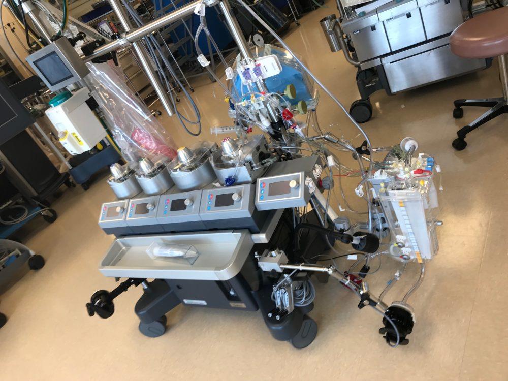
A Pump is Born: 2


Editor’s Note:
In the last post regarding building a new HL machine (A Pump is Born 1), we watched the methodical assembly of a new Terumo System 1. Today, is the second and more challenging (most perfusionists LOVE this part) process of adapting and customizing the HL machine, and putting your own ECC on it- to organize it to the way it best works for you. And of course, we draw on traits crucial to our profession: Improvisation & Innovation…
We create work-arounds- or “jerry-rig the HL and ECC to marry them together. There is always one or two things that will require innovation and outside of the box thinking- in order to bypass (no pun) any obstacles we encounter.
Peace 🙂
![]()
Lets Get This Puppy Ready to Roll…
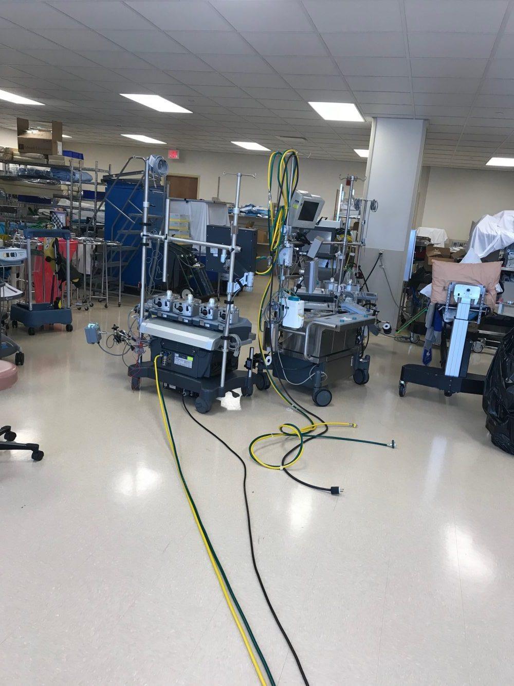
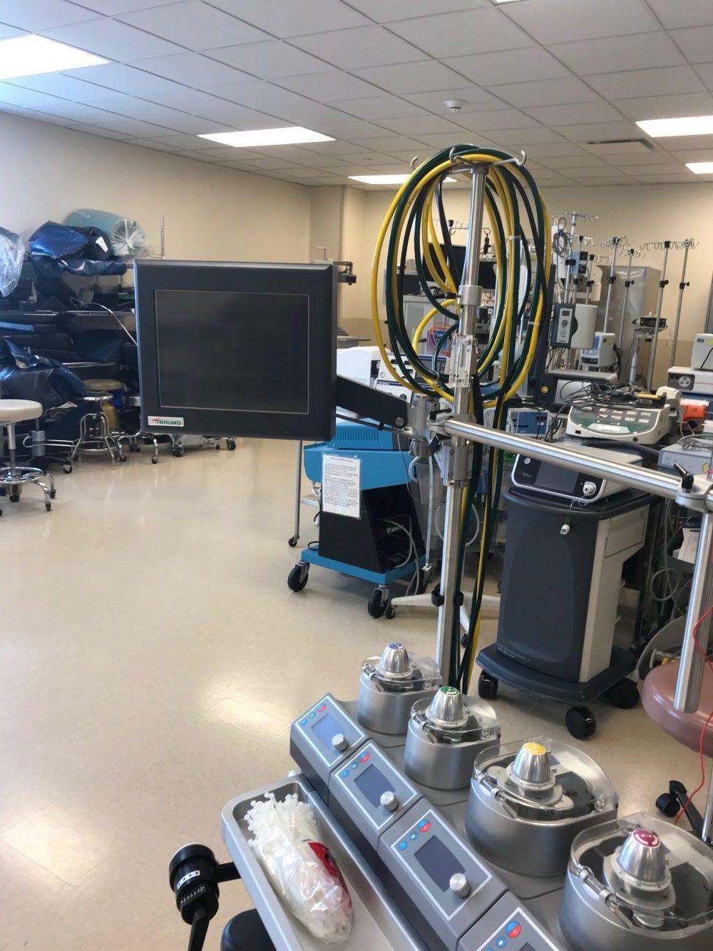
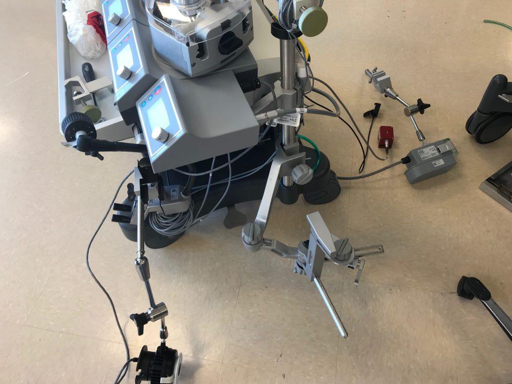
I matched up the power cords and Gas lines to compare lengths and see if there are any issues. In this case- my concern is that the power cord on the new pump is long enough to reach our over head outlet on a moving Boom.
Perfusionists are all about making sure our lines are trimmed well and we try to avoid coils and snarls- hence the excessive reliance on tie-bands.
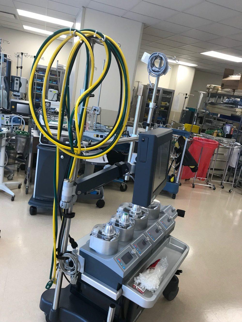
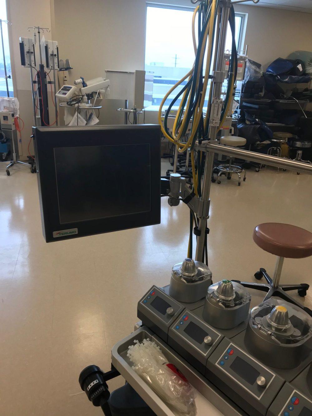
Although it looks sleek- the Monitor is actually way too low when standing up.
Here is the adjustment, to place the monitor at eye level when standing.
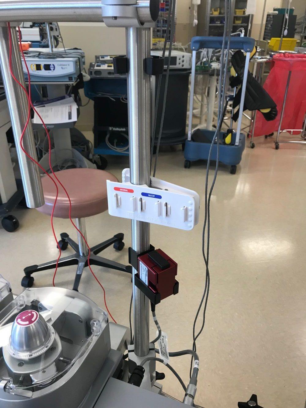
Various items that will be placed more strategically at a later stage of the assembly. (Temp probes, level detectors, and Bubble detector holder…)
The manifold holder has found it’s home already 🙂
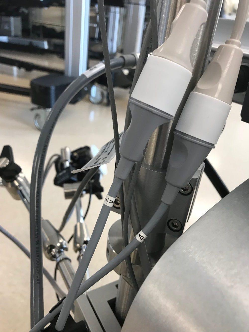
Pressure cable are labeled on both ends and attached to transducers. They will be tested and double checked several times before use. (V stands for cardioplegia- as we had no “C” label.)
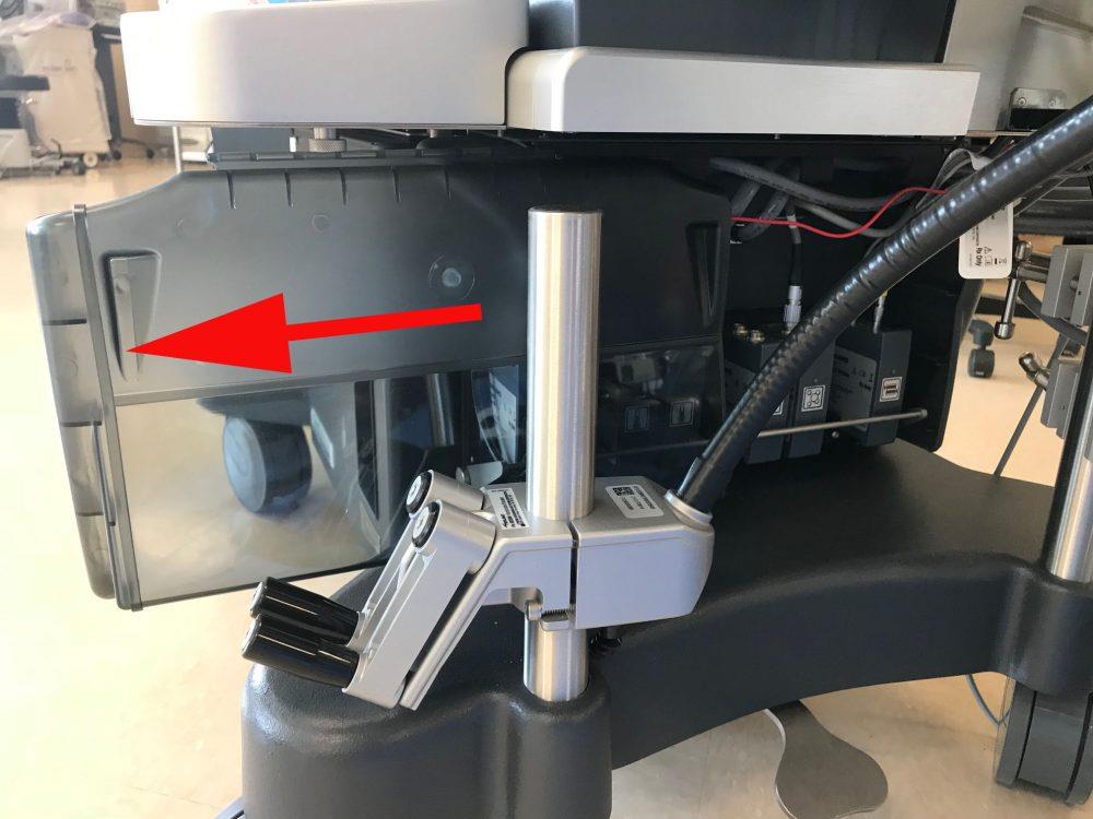
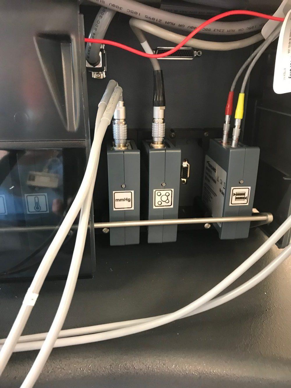
This is a key photo as it shows how to gain access past the plastic shield, to the modules and cable connections located behind. This is a very clumsy and ill designed process consistent with this particular HLM. You have to SLIDE the shield out, it is in a very tight tongue in groove slide- that makes the process jerky- and sometimes the plastic just gets stuck!
There are two objections I have to this method: It is counter-intuitive, because the panel also will lift up slightly- rendering the impression that it opens up by lifting up. Well that’s not the case at all. You have to slide it out sideways and it would be helpful if Terumo at least put a large arrow on these slide plates so the operator knows what direction to push or pull- in order to get it to “open”.
Please note: other than setting up the pump, or modification to the pump, the only other time you will try to access this area- is WHEN YOU ARE ON PUMP AND TROUBLESHOOTING YOUR CONNECTION OR MODULES! A bad time to fumble with a poorly designed plastic cover.
From L>R: Pressure Module; Bubble Detector; Level Detectors
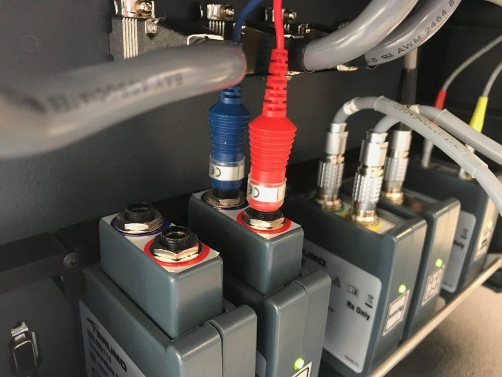
Temperature Probe Module: Note the green LED lights- Green is good, Yellow? Not so much… (be sure to double check to make sure your modules are assigned properly, AND inserted to a tight fit-)
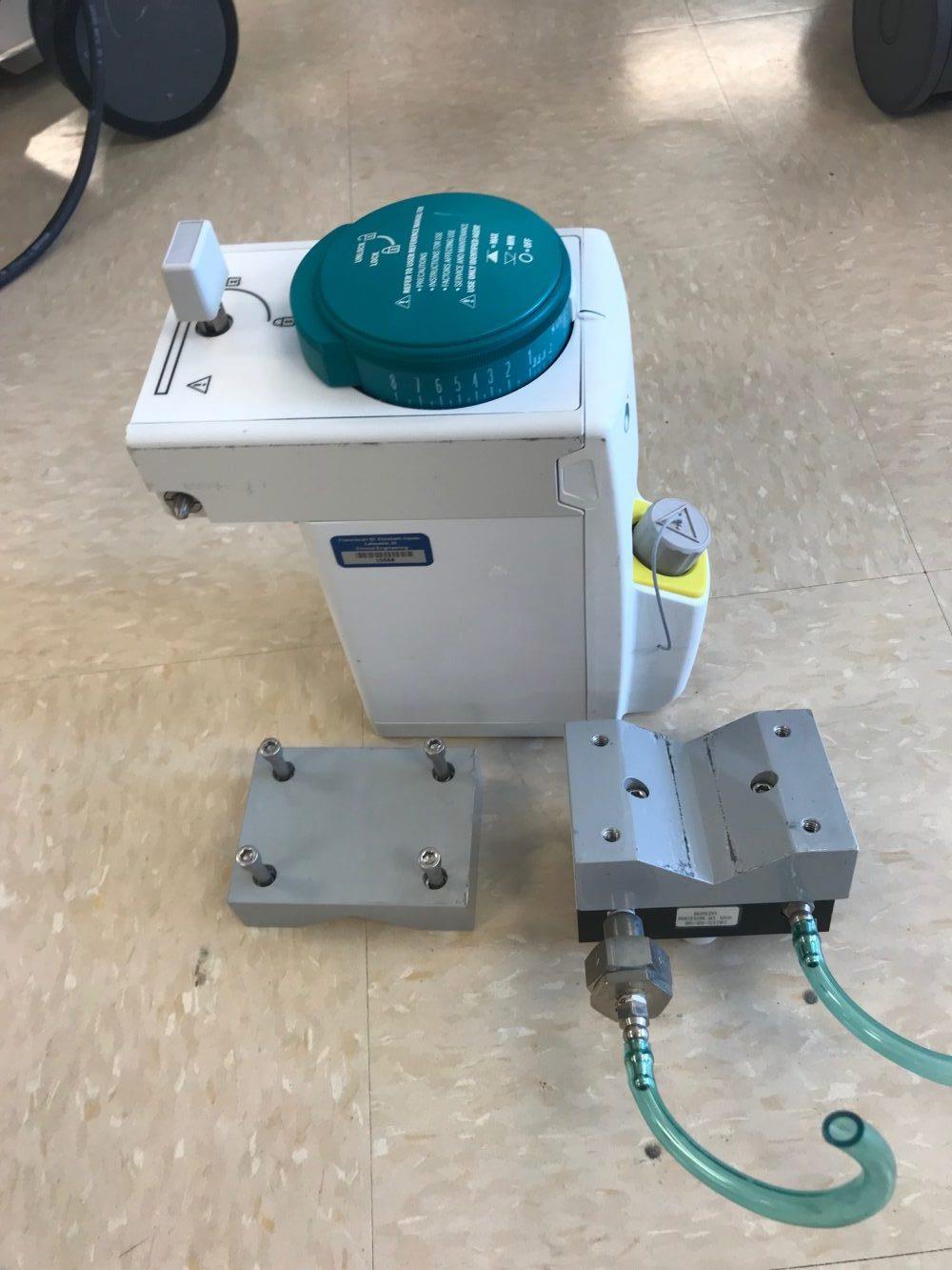
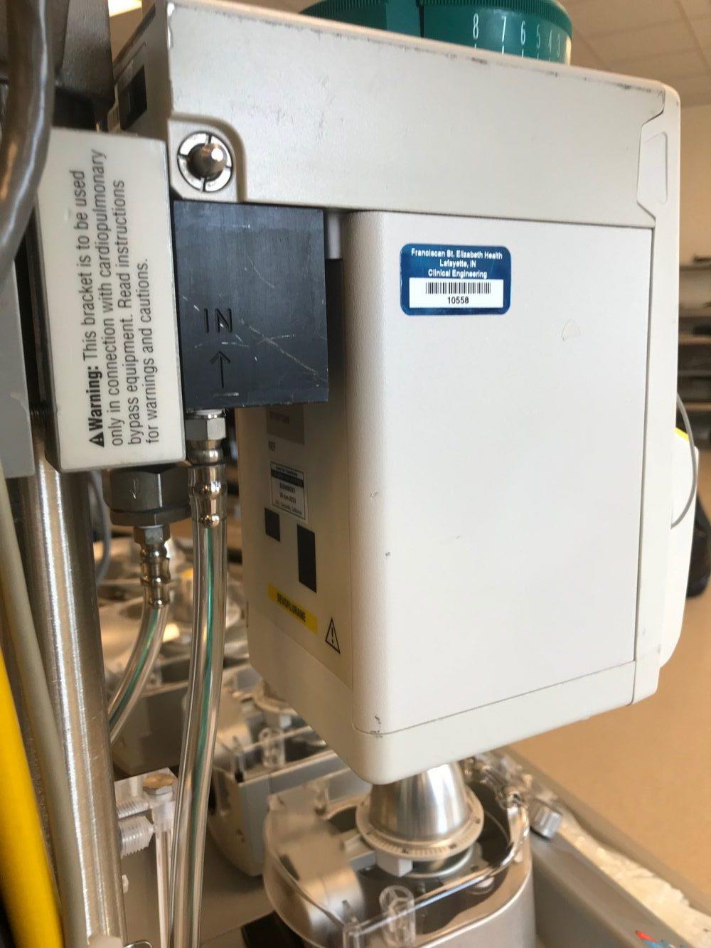
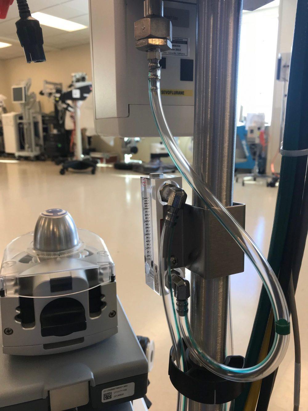
Sevoflurane Blender from old pump…
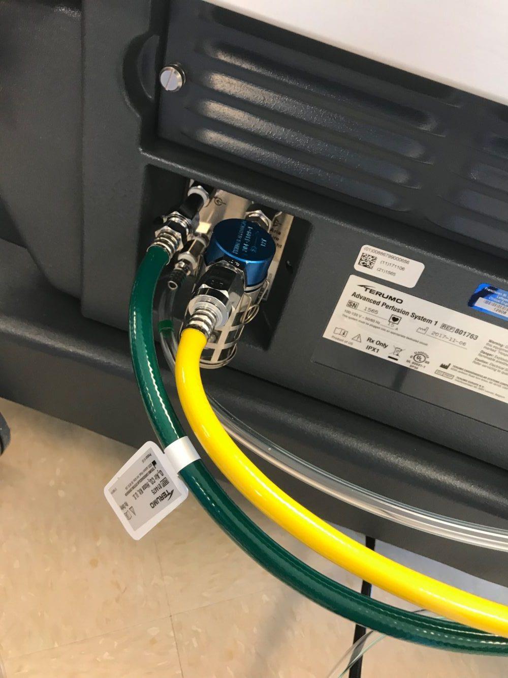
TRACE your gas lines!
Follow air Q direction…
I like putting this Q meter distal to the blender, BECAUSE I have seen blenders obstruct gas Q when engaged, and at least this way- I can quickly evaluate this highly undesirable effect 🙁
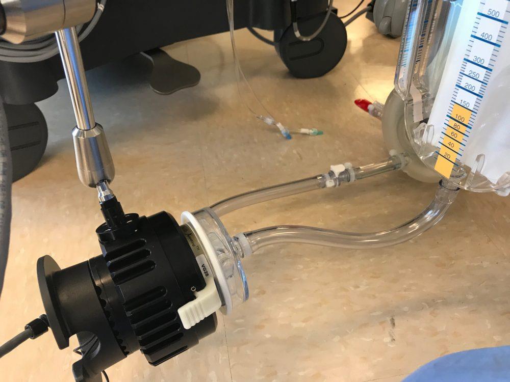
I removed all components erroneous to the Reservoir/Oxygenator holder- just to avoid a visual mess- when trying to get the most uncomplicated fit.
Looks a little tight…
VOILA! A Pump is Born ! 🙂
Peace & Happy New Year
![]()
